Model Railway Operation
The AMBIS lever frame was designed for use on the Eastwell layouts. Co-incidently it was released concurrently with the MSE product.
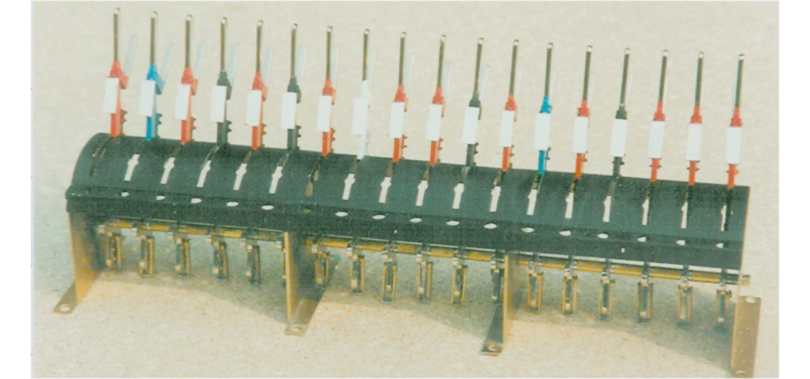
This lever frame was built by David Yule from the Mk1 kit. He plated the (then) brass levers and cut out all the LED pocket holes in this 18 lever frame.
The current lever frame is version three the illustration below is of version two with long and short levers.
As an adjunct to the lever frame mechanical interlocking was designed following a challenge over one exhibition weekend. It can reproduce almost all prototypical interlocking requirements- without modifications, the exception is if signals are held "off" by the lie of points when "holding the road". 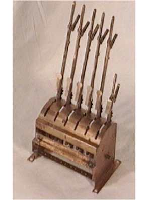
It is quite possible to mount micro switches to operate in conjunction with lever movement, but there are many types of switch and a number of possible locations. One thing to consider is do you want a circuit switched at the beginning or end of the lever movement?
Levers are mounted at 0.5 inch spacing regardless of the number of levers in a frame. This matches the optional mechanical inter locking drive spacing.
The current push button switch options to add to the lever frame available from AMBIS are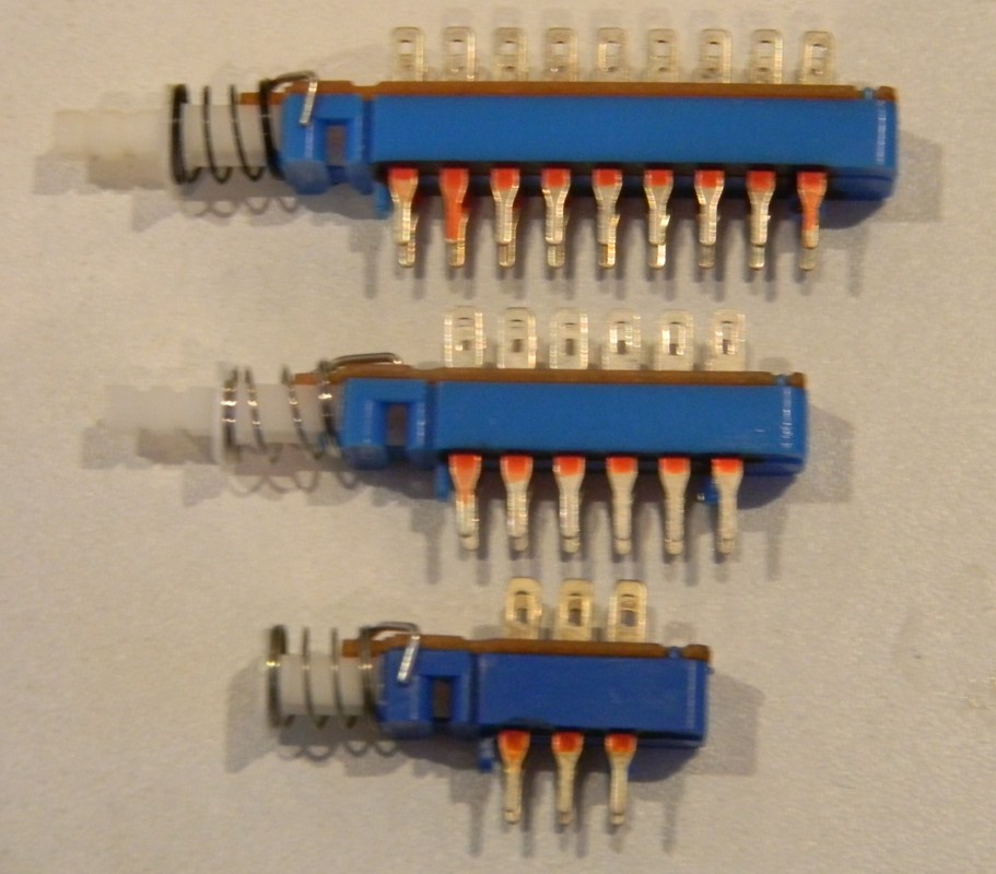
2, 4 or 6 pole two way switches from push button radio systems.
A latching lever (silver) needs to be made inoperative by moving to one side
and the switch button cover mounting (white nylon) should be removed
then the lever in the frame will operate these switches.
NOTE the switch pin spacing is not even for x and y axes.
 The Point Actuating and Locking Mechanism (PALM) mechanism was introduced to lock point switches in place but it can also be used to reduce the throw of a point motor or be part of a very simple operating mechanism - a knotted string and return spring. It uses the same principle as the mechanical locking. This is not an original idea is was used by the NER c1879-80, by Hornby Dublo on its two rail system and many in other circumstances including the prototype - it is a lazy "Z" mechanism.
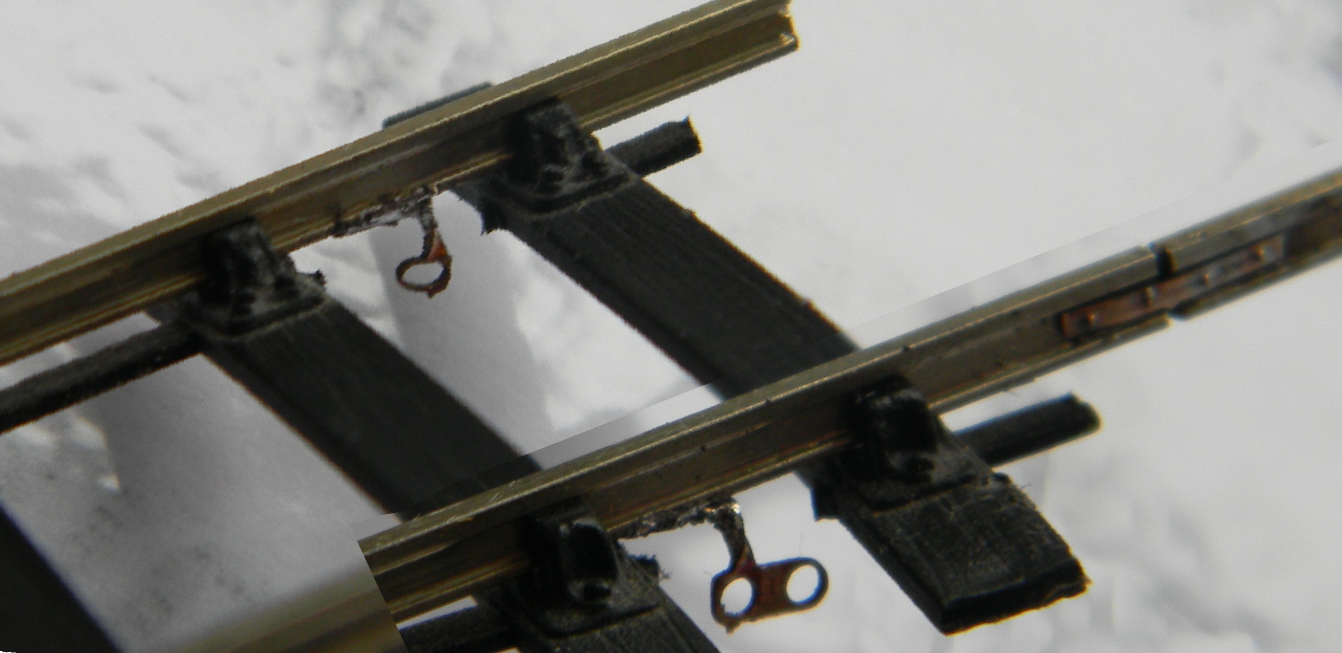
 To support the laying of track carrying traction power a design to attach wires to rails and including a four bolt fishplate etching was introduced in February 2014. This fishplate is more suitable for light railways that it is for main line and track circuited lines. A second bonding only option was introduced later.