Railway trackwork details
One of the long term issues with the Eastwell layouts were stretcher bars - often and incorrectly called "Tie Bars" by most railway modellers.
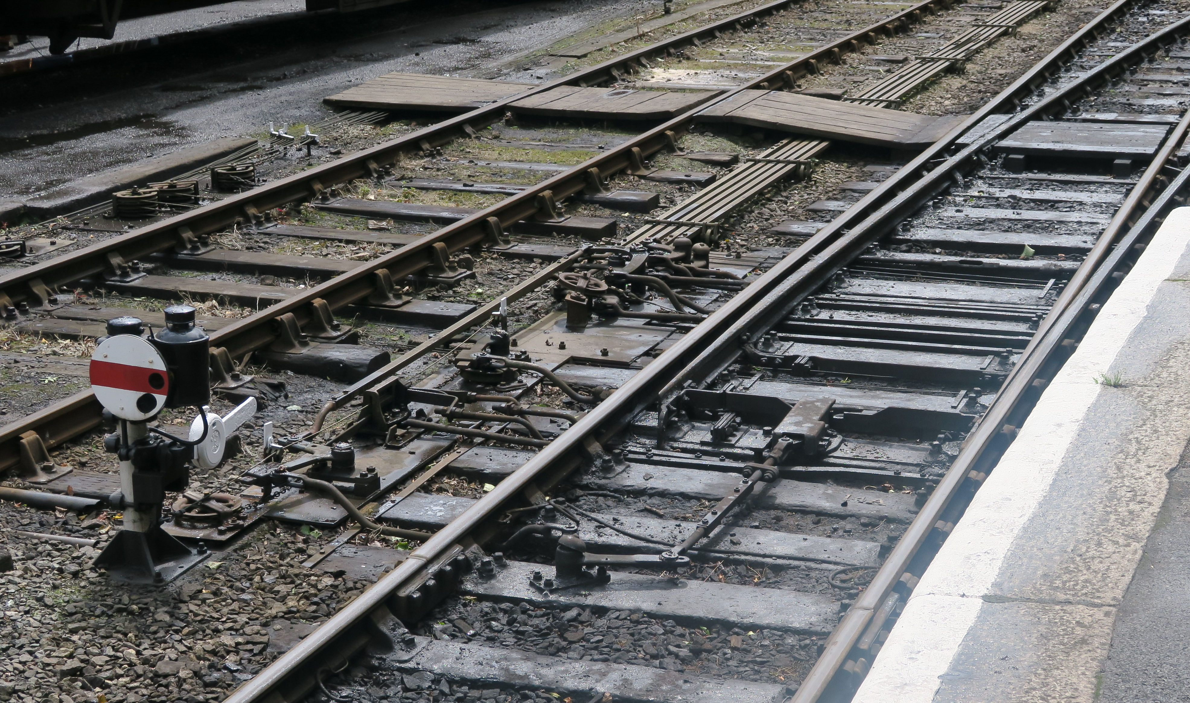
Bodmin Station showing the complexity with point rodding that could exist with even simple trackwork. There is a bolt lock to the point switch and a selector connected to the ground signal (or "dod"), and accommodating cranks used on the point rodding runs, but no sign of any compensators at this location.
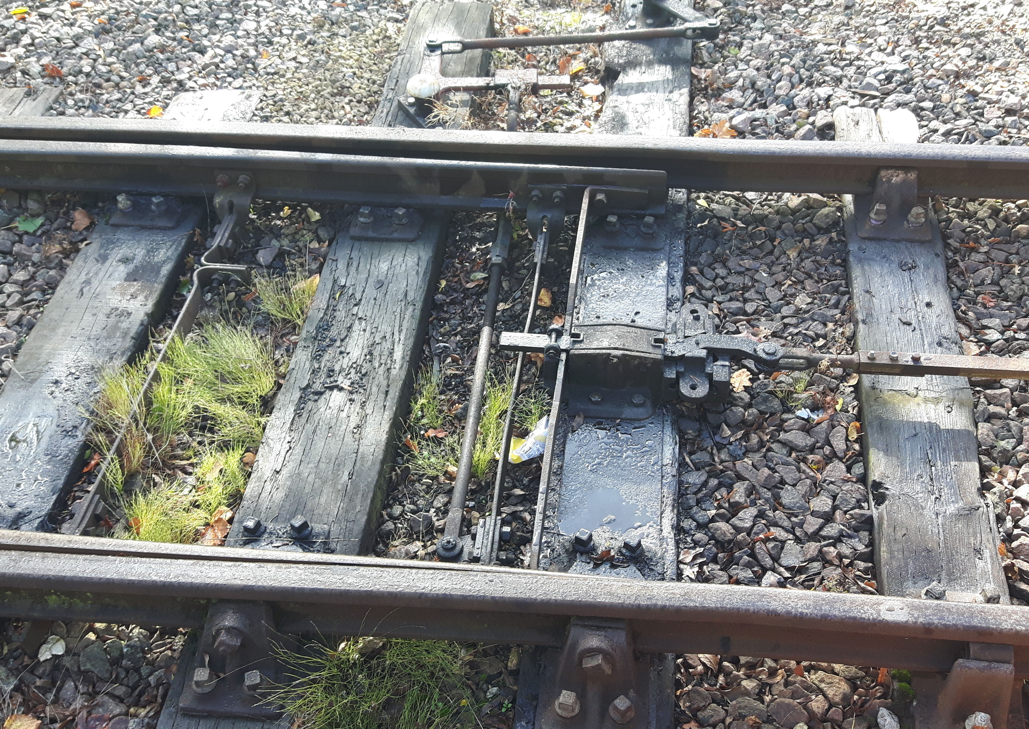
A bolt lock in use on the Mid Suffolk Light Railway shows stretchers are independent of the point lock mechanism and the switch operating rod is connected to the most distant switch blade. Note the adjusting crank inserted into the rodding run.
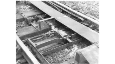
The illustration shows parts of a facing point lock mechanism with its metal cover lifted off to one side including flange detector and in the lower foreground a flat stretcher bar.
Whilst prototype stretcher bars have some flexibility built into them that is not often the case with model trackwork. The usual answer has been to use a solid soldered joint between switch blade and stretcher and make it as strong as possible. Model trackwork often involves a greater length of travel for switch blades than prototypes and this increases the slight, very slight, change in angle between switch blade and stretcher as the points are changed. This induces stress in the connection between switch blade and stretcher and this joint can fail at embarrassing moments.
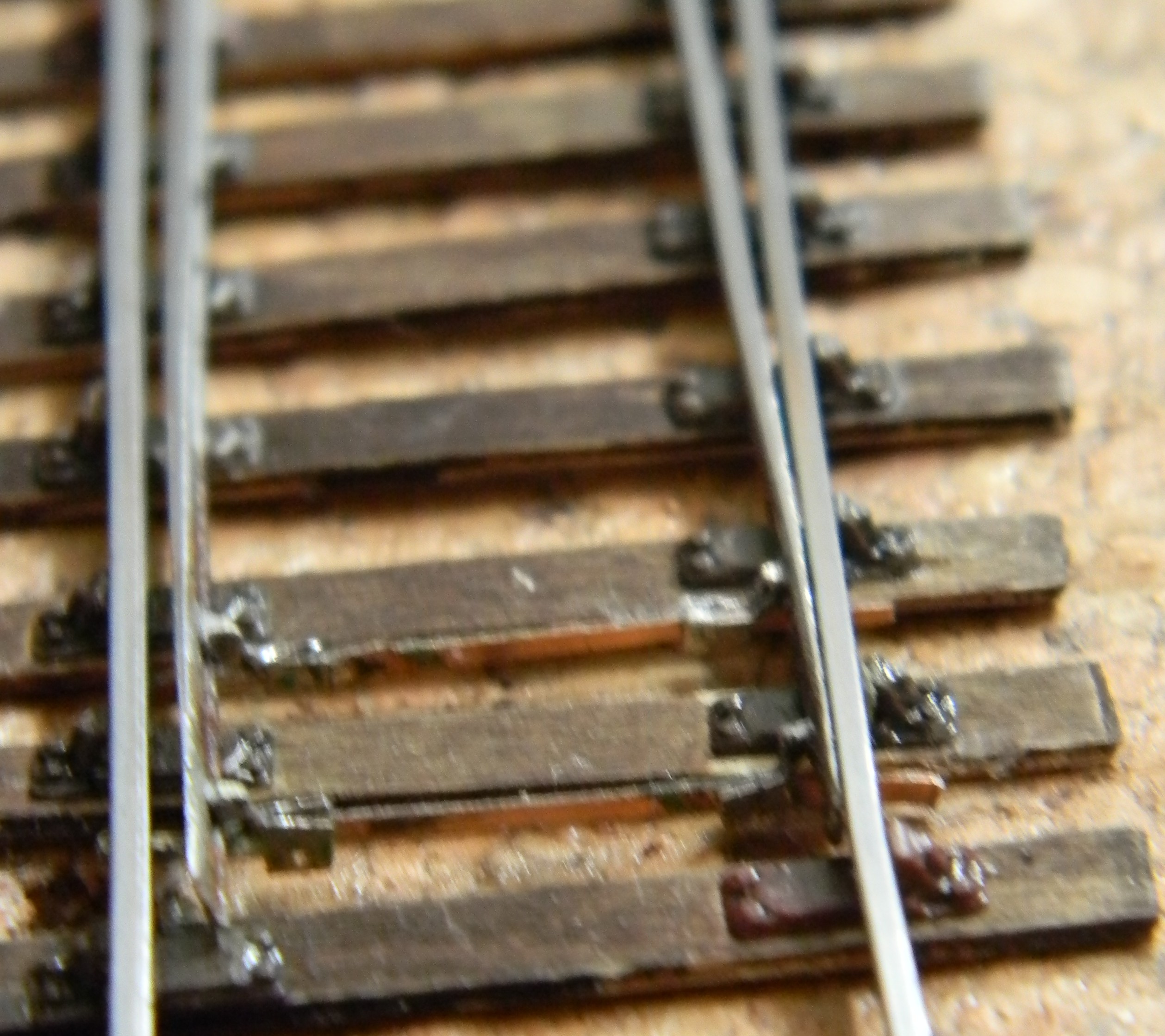
The first AMBIS stretcher design replicates the vertical flat bar stretcher which we think was first introduced in the 1930's on main lines and had become quite common by the 1960s. We believe it may parallel the general introduction of track circuits or perhaps flat bottom rail introduced c1936 by the LMS. The illustration shows a stretcher in 7mm scale constructed using wires, not etched components.
The Mk2 bar stretcher product includes point assembly components for "EM" and "P4" track standards and includes a version for flat bottom or larger section rail than code 75 bullhead.
The earlier prototype stretcher designs used what appears to be gas pipe - a rod just over one inch in diameter and was still quite common in sidings in the 1960's. A version of the stretcher bar component was introduced in 2009 to allow the rod version to be made. Please note the GWR used a different design of a rod stretcher than many other railways.
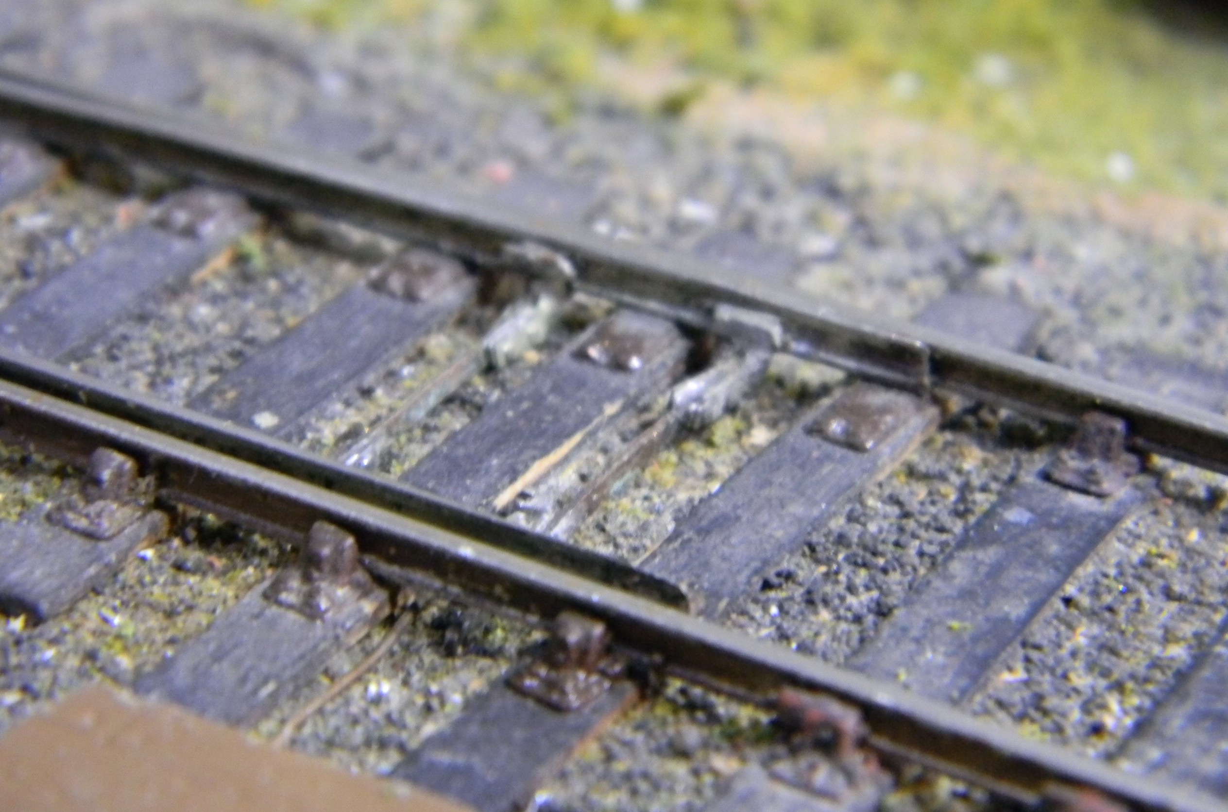
A Mk4 stretcher bar product was made available in 2012 in both 4mm and 7mm scales. The illustration uses the 7mm:1 ft scale version which is just larger than the 4mm:1 ft version. Then  the Mk4 flat stretcher bar was changed to Mk.5 - a phosphor-bronze version in 0.006 so the thickness when attached to the switch blade was not so noticeable.
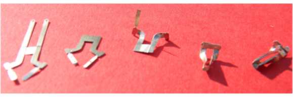
Left a 4mm scale bar stretcher - Mk.3 version, right a rod stretcher in 4mm:1ft scale.
Both screw coupling links, stretcher connections and the point rodding items are likely to need the holes clearing to take 0.33mm rod or the smallest pins we have been able to source - 0.45mm diameter - use a very fine cutting broach for clearing out the holes. As an alternative we can also supply headless pins and these are available in smaller diameters. The pins can be used to fix rodding cranks in place, whilst for other uses the point of the pin will need to be removed, usually after assembly.
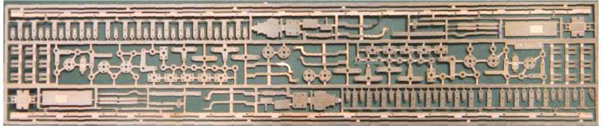
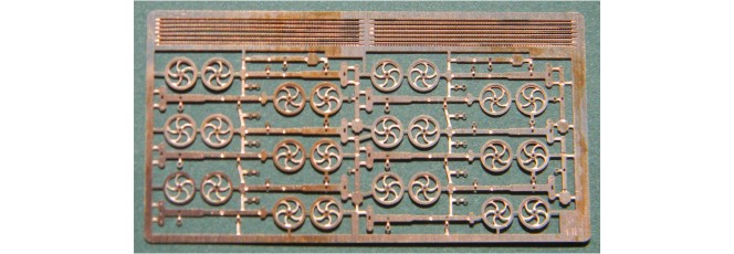
AMBIS started to introduce reproductions of a full set of rodding and crank details including facing point locks and mechanical detectors during 2012. In the 1990's a version of the facing point lock was produced but had one design fault and was withdrawn. The first stage of this new range were channel section rodding, new stools, the facing point lock, bolt lock,accommodating cranks, adjustable cranks and rodding cranks. This was then supplemented by signalling wire pulleys. A full set of the cranks and rodding etches images is provided on the Downloads and Details page.
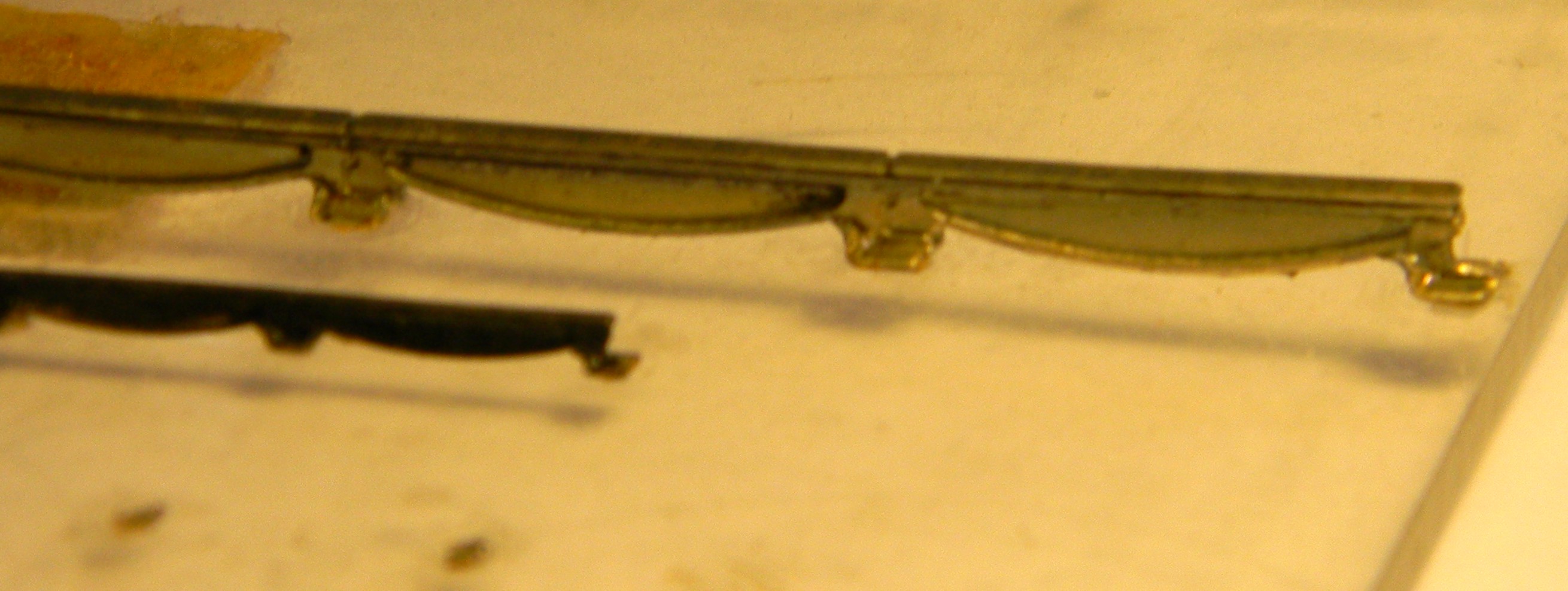
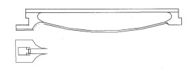
As a scenic item an etch for fishbelly track was introduced, although it was used as working track on a 1840's layout that was abandoned due to lack of storage space. To complement this a plateway "rail" etching was introduced in 2012. Below are the 7mm and 4mm scale versions.
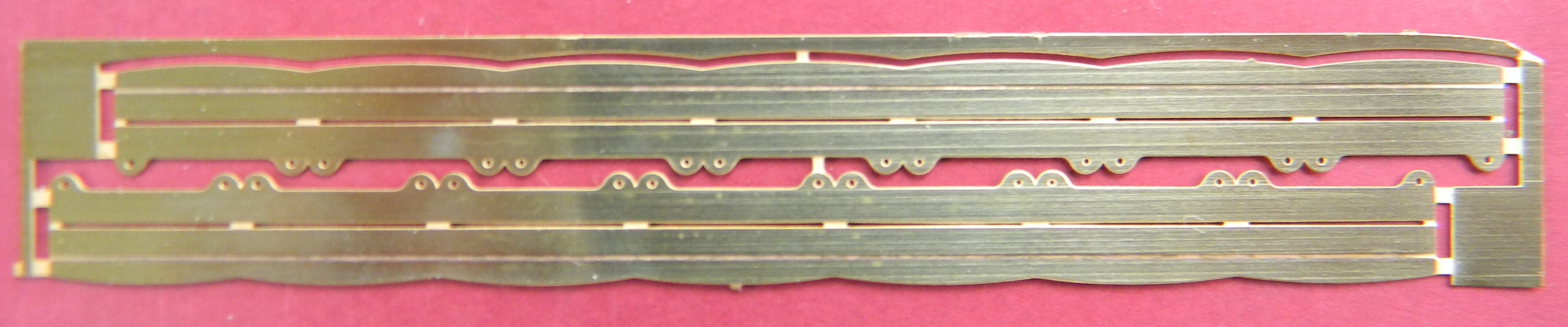
E ssentially a tram track rail has a narrow flatbottom section with a flangeway grove it the rail head. The simulated tram rail components are for the conversion of code 75 bullhead rail. It is adaptable for a range of wheel standards and guages - OO finescale to P4 wheels and will also accept S7 wheels.
Once we can make satisfactory masters or by using 3D printing a small run of concrete sleepers as used in the Corby internal railway system will be made available. There were at least two designs we know of one for flat bottom and the other for bullhead rail. These were found stacked at the Rutland Railway Museum.
References
1) Fishbelly rail -
2) Plateway track
3) Lewis - "Railway Engineering" 1932, reprinted by P Kay